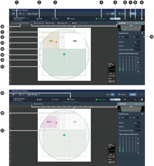
Overview of the microphone settings screen
Selecting a microphone will switch to the microphone settings screen.

-
Microphone name / model name
Displays the microphone name and model name. The microphone name can be changed using “Rename” in the device list menu. Click to select and display settings for a different microphone.
-
Beam Tab
Click to switch to the display for the microphone beam zone settings.
-
Audio Tab
Click to switch to the display for the microphone audio settings.
-
Microphone connection status
Displays the microphone connection status.
Connected: A connection was established normally.
Disconnected: Not connected with the microphone.
Missing: A connection error occurred.
Power Save: Connection established in power save mode. -
Online/Offline
Click to temporarily take the connection for an online microphone offline. Click again to switch the microphone back online. Select the settings data to be reflected and click “OK”. It may take several minutes to save presets when reflecting settings from the software application to the microphone.
-
Mute
With each click, the selected microphone switches between muted and unmuted.
-
Audio-Technica LINK status (ATND1061LK only)
Displays the Audio-Technica LINK connection status.
 : Audio-Technica LINK is not connected correctly.
 : Audio-Technica LINK is connected correctly.
 -
Error status
Displays the error status.
 : No error is present.
  : An error is present. Clicking the triangle mark below the icon displays a description of the error. After checking the description of the error, move the cursor away from the icon, and the triangle mark will disappear.
 -
Settings & Maintenance
Displays the microphone’s Settings & Maintenance screen.
-
Zone Layout Preset
Click to select a zone layout preset for the selected microphone. For details, see Zone layout presets.
-
Beam toolbar
If “Beam” is selected, the toolbar appears.
-
Exclusion Zone
This is the area set as the Exclusion Zone. “EX” is displayed.
-
Priority Zone
This is the area set as the Priority Zone. “CH2” to “CH6” are displayed.
-
Position marker
A position marked using the position marker. Numbers are shown in the order marked.
-
Coverage Zone
This is the area set as the Coverage Zone.
-
Microphone pickup area
The microphone scans for sound and displays areas in which sound pickup is possible. The size of the microphone pickup area will depend on the microphone installation height and settings for the sound pickup angle and view level.
-
Microphone icon
Displays the microphone installation position.
-
Context panel
Displays microphone settings.
-
Camera Tab
Click to switch to the display for the microphone Camera Area settings.
-
Camera toolbar
If “Camera” is selected, the toolbar appears.
-
Camera Area
This is the area set as the Camera Area. Group numbers “GR1” to “GR8” are displayed. Camera Area is only displayed when “Camera” is clicked to switch to the display for Camera Area settings.